

When a measured building survey involves a complex structure, something with intricate internal layout, multiple systems running through it, or a requirement for millimetre-level accuracy. The process of producing the finished drawings involves more steps than many clients realise. The end result, a set of clean, detailed 2D CAD plans, represents the output of a workflow that begins long before anyone opens a drawing package.
This post walks through how we approach that process at GeoShape Surveys, and why the combination of laser scanning and skilled CAD production makes a significant difference to the quality and reliability of the finished deliverable.

3D isometric CAD view produced from point cloud scan data, showing the full internal layout of a complex industrial structure.
What Is a Point Cloud?
A point cloud is a three-dimensional dataset generated by a laser scanner. The scanner emits laser pulses in every direction and records where each pulse reflects back from a surface. Do this millions of times per second and you end up with an extraordinarily dense cloud of measured points, each one representing a precise location in three-dimensional space.
For a complex structure such as a generator enclosure, a plant room or a multi-storey building, the point cloud captures everything: walls, ceilings, floors, pipework, structural steelwork, doors, windows and any equipment inside the space. Every surface that the scanner can see is recorded to sub-millimetre accuracy.
The point cloud itself is not the deliverable. It is the raw material from which the drawings are produced.
Registering and Processing the Scan Data
Most survey jobs require scans taken from multiple positions to ensure full coverage of the structure. The individual scans are then registered, aligned to a common coordinate system, so that they combine into a single, seamless dataset representing the whole building or asset.
This registration process requires care and precision. Any error at this stage carries through into the finished drawings. Once registration is complete, the surveyor has a verified, accurate 3D model of the structure to work from.
Producing the 2D CAD Drawings
With a verified point cloud in place, the drawing production process begins. Working within the point cloud, the CAD technician traces the geometry of the structure to produce accurate 2D drawings at the required level of detail.
For a floor plan, this means extracting a horizontal slice through the point cloud at the appropriate height and tracing the walls, openings, fixed equipment and any other features the client needs recorded. For an elevation, a vertical slice is taken and the external or internal face of the building is drawn from the scan data.
On technically complex projects such as a detailed survey of an industrial enclosure containing a generator, switchgear, pipework and fire suppression systems. This process requires experienced operators who understand both the survey data and how to present it clearly in a CAD drawing. The finished plans need to be not only accurate but legible and usable by the engineers, designers or contractors who will work from them.
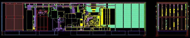
Detailed plan and elevation views of a complex industrial unit, extracted from point cloud scan data.
Why This Approach Produces Better Results
The alternative to scanning is manual measurement using a distometer and tape, which produces a set of site notes that are then used to construct drawings back in the office. The accuracy of the finished drawings depends entirely on the accuracy and completeness of those notes.
Scanning removes that dependency. The point cloud is a permanent, verifiable record of what the surveyor measured on site. If a dimension needs to be checked, the scan data can be revisited. If a feature was missed in the initial drawing, it can often be extracted from the existing dataset without a return site visit.
For clients who need to rely on survey drawings for engineering, design or construction purposes, that reliability matters. Drawings produced from a verified point cloud are, quite simply, more trustworthy than drawings produced from manual notes, particularly on complex structures where the margin for error is low.
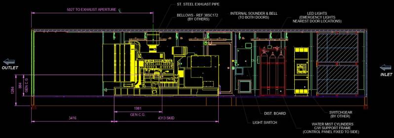
Annotated internal layout drawing with precise dimensions and component references: the kind of detail that would be difficult to capture accurately by hand.
What the Client Receives
At the end of the process, the client receives a set of 2D CAD drawings in their required format (typically DWG or DXF), along with PDF versions for reference. Depending on the scope of the job, this might include floor plans at one or more levels, external and internal elevations, cross-sections, and detail drawings of specific features.
The drawings are produced to a specified scale and level of detail agreed at the outset, so the client knows exactly what they are getting and can put it straight to use.
At GeoShape Surveys, our team handles the full process from scanning through to finished CAD deliverable. If you have a complex structure that needs to be accurately recorded, or if you need detailed 2D drawings produced from an existing scan dataset, get in touch to discuss what is involved.
Contact GeoShape Surveys
At GeoShape Surveys we provide setting-out services for construction and development projects across the South West. Whether you are at the planning stage or about to break ground, we are happy to discuss what accurate setting-out involves and how we can support your project. Get in touch with our team to find out more.